
How to Choose the Right Solder Preforms for Precision Soldering
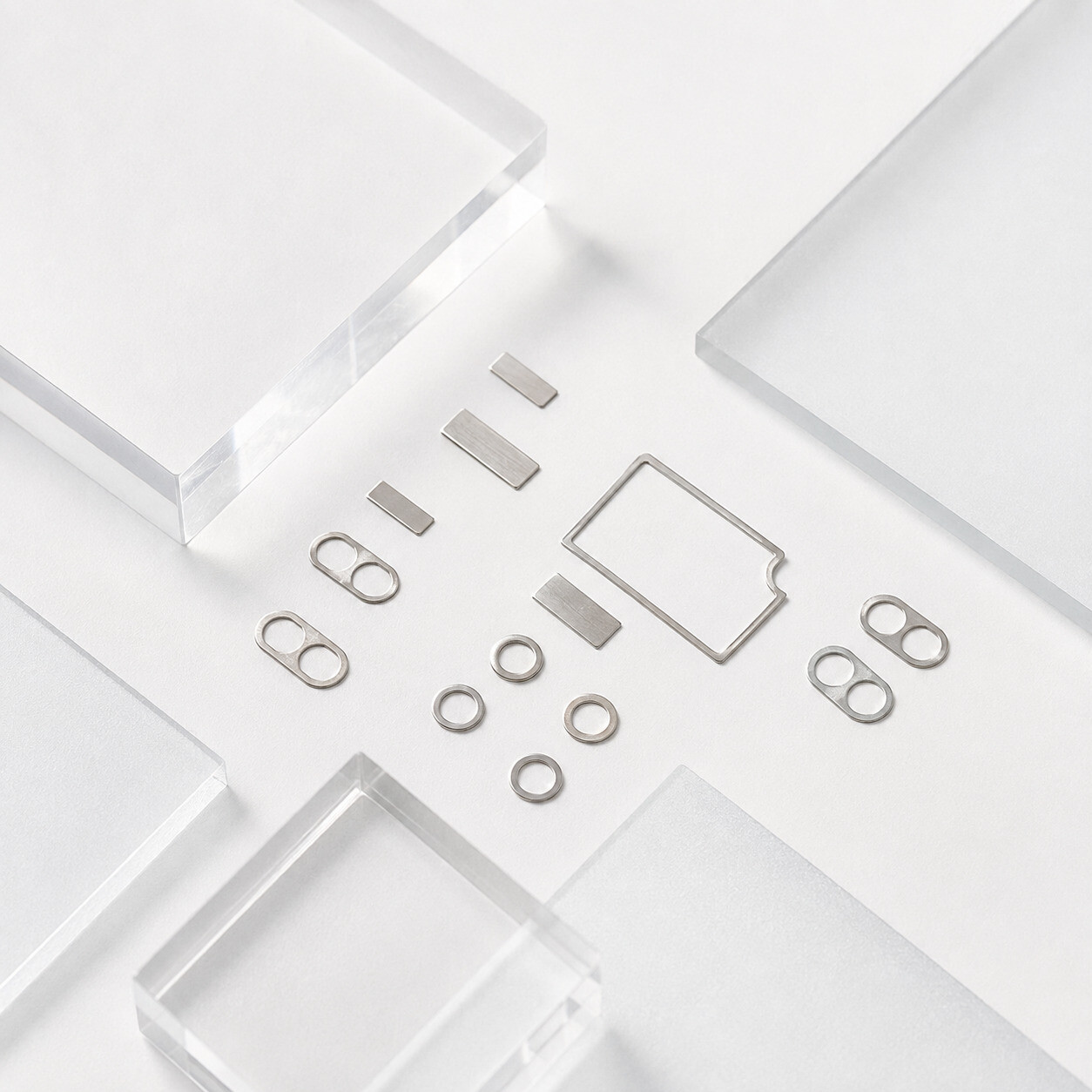
In many electronic assemblies, the challenge is not simply getting solder onto a joint. The real challenge is applying the right amount of solder in the right position, consistently. Too little solder may leave an incomplete or mechanically weak joint, while excessive solder can increase the risk of bridging, overflow or dimensional variation.
For applications that require a defined metal volume, solder preforms provide a practical alternative or supplement to solder paste and solder wire. Because each preform is manufactured to a specified geometry, it can help engineers control solder volume before reflow and improve process repeatability.
What Is a Solder Preform?
A solder preform is a solid piece of solder alloy manufactured in a predetermined shape, size and thickness. It is positioned at the joint and heated until the alloy melts, wets the compatible surfaces and forms the solder connection.
Preforms can be produced as rectangles, squares, discs, washers, frames or application-specific shapes. They may be supplied as pure alloy or with a controlled flux coating, depending on the surface condition, atmosphere and soldering process.
Why manufacturers use solder preforms
- Defined and repeatable solder volume
- Consistent placement and joint geometry
- Additional solder for joints where paste alone may be insufficient
- Pure-alloy and flux-coated process options
- Compatibility with manual placement or automated pick-and-place, depending on packaging
- Custom geometries for unusual pads, terminals and assemblies
Solder Preforms vs. Solder Paste and Solder Wire
Solder paste remains the standard choice for high-volume SMT printing, while solder wire is widely used for hand soldering, robotic soldering and rework. A solder preform is especially useful when the process needs a precise, repeatable amount of metal that is difficult to deliver through printing, dispensing or wire feeding alone.
| Material Form | Main Strength | Typical Use |
|---|---|---|
| Solder Preform | Defined solid solder volume and geometry | Precision joints, solder fortification, terminals and custom assemblies |
| Solder Paste | Efficient stencil printing for many SMT joints | Surface-mount PCB assembly and dispensing |
| Solder Wire | Flexible point-by-point solder delivery | Hand soldering, robotic soldering and repair |
These materials are not always competing choices. For example, a preform may be placed with solder paste to increase the total solder volume in a selected joint. The best option depends on the component, joint design, available equipment and required production rate.

Six Factors to Consider When Selecting Solder Preforms
1. Determine the required solder volume
Begin with the joint area and the target bond-line thickness. For a simple rectangular preform, the initial solid volume can be estimated from length × width × thickness. The final specification should also consider pad geometry, component stand-off, wetting area, process losses and the acceptable fillet shape.
This is one of the main advantages of a preform: instead of relying only on a variable printed or dispensed deposit, the designer starts with a defined piece of solder alloy.
2. Choose the alloy for the assembly
The alloy determines the melting range and contributes to the mechanical, thermal and regulatory characteristics of the finished joint. Common options may include lead-free Sn-Ag-Cu alloys such as SAC305, tin-lead alloys where legally permitted, low-temperature Sn-Bi systems and other application-specific compositions.
Selection should be based on the substrate and finish, peak process temperature, service temperature, thermal cycling requirements, compliance needs and compatibility with any solder paste already used in the assembly. Do not select an alloy by melting point alone.
3. Match the geometry to the joint
Rectangular chip-style preforms are convenient for many electronic assemblies and can be presented to automated placement equipment. Discs and squares suit flat bonding areas, washers fit around pins or terminals, and frames can follow the perimeter of lids or packages. A custom profile may be the better choice when the available space or wetting area is irregular.
The preform should be easy to locate and should not interfere with surrounding components before reflow. Shape, flatness and edge condition can therefore be as important as nominal volume.
4. Decide whether flux coating is needed
A pure-alloy preform can be appropriate when flux is already supplied by solder paste, when a separate fluxing step is used or when the process runs in a suitable controlled atmosphere. A flux-coated solder preform places flux directly on the solder piece and may simplify application in processes that need localized flux.
The correct choice depends on surface oxidation, metallization, heating method, atmosphere, residue requirements and cleaning process. Flux chemistry and coating level should be evaluated with the actual assembly rather than selected as an isolated specification.
5. Define realistic dimensional tolerances
Tighter tolerances can improve control where solder volume and bond-line thickness are critical, but they may also affect manufacturing complexity and cost. Identify which dimension directly controls joint performance, then specify the tolerance that the application genuinely requires.
6. Select packaging for the placement method
Packaging affects handling, protection and production efficiency. Bottle packaging can suit manual use or compatible feeding methods. Waffle trays keep individual preforms organized for manual or automated pickup. Tape-and-reel packaging is commonly selected for continuous feeding and automated pick-and-place operations.
When requesting a quotation, describe how the preform will be picked, oriented and placed. This helps the supplier evaluate both the part and the packaging as one production solution.
Typical Applications of Custom Solder Preforms
Adding controlled solder volume to selected SMT or through-hole joints.
Bonding components where joint thickness and thermal performance require process control.
Providing a repeatable solder charge around pins, contacts and connection areas.
Supporting compact assemblies with controlled solder placement.
Creating defined solder layers in geometry-sensitive assemblies.
Joining components with discs, washers, frames or special profiles.
Standard Jufeng Chip-Style Solder Preforms
Jufeng Solder supplies standard chip-style solder preforms for precision electronic assembly, controlled solder volume and automated placement. Current product options include the following models:
For non-standard projects, Jufeng also supports OEM customization for alloy, size, shape, flux coating and packaging. Available packaging options include bottle, waffle and tape and reel, subject to the selected geometry and order requirements.
Information to Send for a Custom Solder Preform Quote
Providing complete project information helps shorten the evaluation process. Where possible, include:
- Preferred solder alloy or required melting range
- Drawing with length, width, thickness and tolerances
- Required shape, including inner and outer dimensions for washers or frames
- Pure-alloy or flux-coated requirement
- Substrate materials and surface finishes
- Heating method and atmosphere
- Manual or automated placement method
- Preferred packaging, sample quantity and estimated production volume
Frequently Asked Questions
Can solder preforms be used with solder paste?
Yes. In selected assemblies, a compatible preform can be placed with solder paste to add a controlled amount of metal where the printed deposit alone does not provide the required solder volume. Alloy, flux and reflow compatibility should be confirmed through process testing.
Are lead-free solder preforms available?
Yes. Lead-free alloys such as SAC-based compositions can be manufactured as solder preforms. The final alloy should be selected according to the process temperature, joint materials, reliability target and applicable regulations.
Should I choose pure-alloy or flux-coated preforms?
Choose according to the complete soldering process. Pure-alloy preforms may work with solder paste, separately applied flux or a controlled atmosphere. Flux-coated preforms can deliver flux directly at the joint. Surface finish, oxidation, residue and cleaning requirements must also be considered.
Can Jufeng manufacture custom shapes and dimensions?
Jufeng supports OEM solder preform projects involving custom alloys, dimensions, shapes, flux coating and packaging. Feasibility and tolerances are evaluated according to the drawing, alloy properties, geometry and order requirements.
Discuss Your Solder Preform Project with Jufeng
Send us your drawing, alloy requirement, dimensions, tolerance, flux preference, packaging method and estimated quantity. The Jufeng Solder team can evaluate a standard or custom solder preform solution for your assembly.
View Jufeng Solder PreformsCopper Via Filling Paste for TGV and HDI: JL-CS-F01
Why Is SAC305 Solder Paste So Widely Used?
Related Article
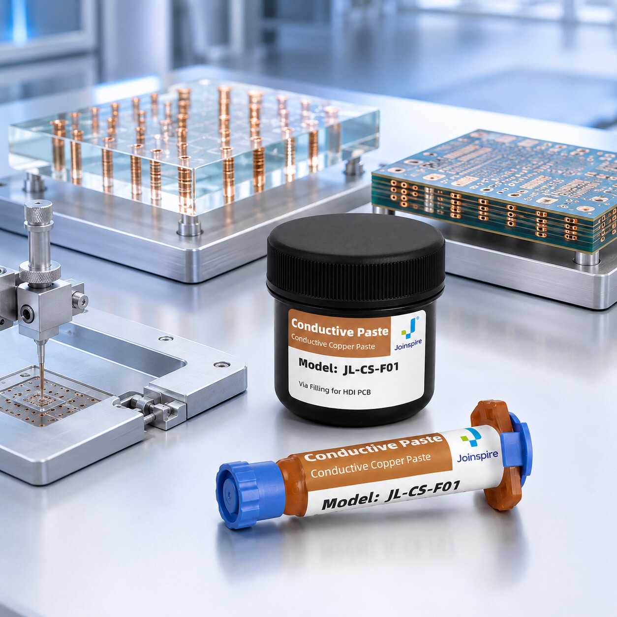
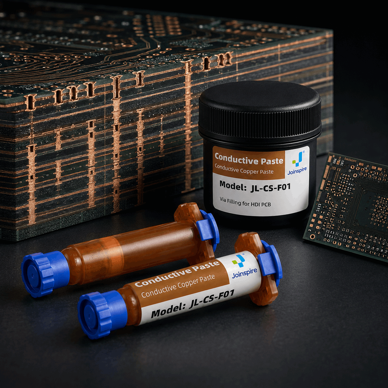

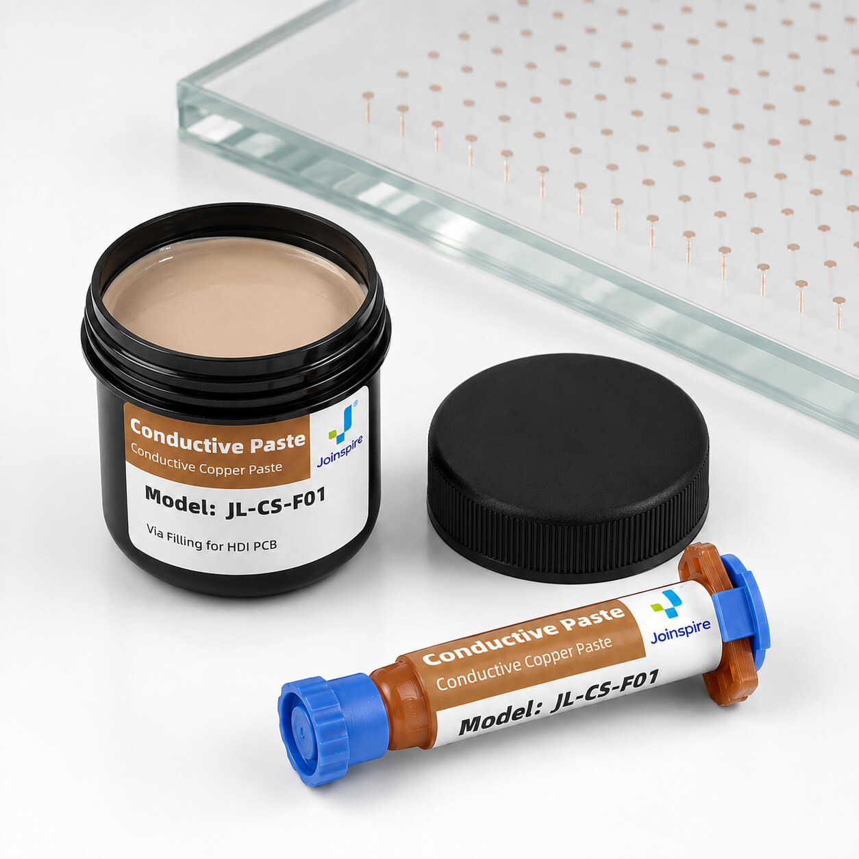
Jufeng JL-CS-F01 copper via filling paste is a single-component conductive resin material developed for via plugging and filling.
